Bends are the most typical feature of sheet metal parts and can be formed by a variety of methods and machines which negate the absolute need for some of the below tips.
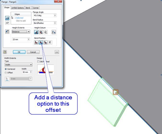
Sheet metal flange height.
Previous editions covered economic order quantity in batch production and the accuracy of things made from rolled sheet stock.
Design for manufacturability sheet metal guidelines bends for the ease of manufacturing multiple bends on the same plane should occur in the same direction.
Offsets are used to create z shaped profiles in sheet metal parts.
The minimum distance between two counterbores is eight times the material thickness.
Sheet metal parts with a minimum of 0 9mm to 20mm in thickness can be manufactured.
Step processing method some of the lower profile sheet metal z shaped steps are bent and the processing manufacturers often use simple molds to machine on punch presses or.
In low carbon steel sheet metal the minimum radius of a bend should be one half the material thickness or 0 80 mm 0 03 inch whichever is larger counterbores.
Next month concludes with the pros and cons of hems jogs and forming tools.
When designing parts for laser cutting one should not make holes smaller than the thickness of the material.
Metal thickness 2024 0 aluminum formed before heat treatment.
Determine your minimum bend by measuring the distance from your closest feature i e.
Choose a bend radius that matches your minimum bend.
Minimum sheet metal flange bend length is required to avoid cracks in the bending area.
If you have any questions or want to discuss your design contact us.
A cutout or the edge of your flange to your bend.
Relief height is generally kept greater than two times of sheet thickness plus bend radius.
Too small a flange height that is the use of a bending die is also not conducive to forming generally the height of the flange is l 3t including the wall thickness.
0 304mm from top of sheet to top of form and recommend an offset of 0 030 in.
Bends in sheet metal are manufactured using sheet metal brakes.
Height of curved flange min.
Avoid large sheet metal parts with small bent flanges.
We offset height tolerance at 0 012 in.
Columnist gerald davis continues a discussion of 3 d cad and precision sheet metal manufacturing in part iii of a four part series focusing on design guidelines for sheet metal.
Height of curved flange min.
Thick ness min bend radii min.
In low carbon steel sheet metal the minimum radius of a bend should be one half the material thickness or 0 80 mm.
We are here to help.
Thick ness min bend radii.
Avoid large sheet metal parts with small bent flanges.
However for typical parts meant to be cost effective and easily produced the following tips should be useful.
A 1 degree tolerance on all bend angles.